Due to popularity of additive technologies, lower prices of simple FDM (FFF) 3D printers, and wide availability of free 3D models databases such as https://www.thingiverse.com/ or https://www.myminifactory.com/, many amateurs of 3D printing technology may want to create their own models or modify the existing ones to suit their purpose, expectations or taste.
To create a 3D model you do not need to have highly specialized and therefore expensive modeling software. You can use free programs like blender or online sketchup. However, making a visually good model may not be the same as a model adapted for 3D printing. In the following article I will try to present what rules should be followed when 3D modeling for 3D printing, so you can avoid many mistakes. If you ask a professional company to adapt a model for 3D printing in extreme cases it may take more resources than creating a new one. Sometimes it is quicker and easier to make a model from scratch based on an uploaded model with errors than trying to fix an existing one.
General requirements for models designed for 3D printing:
The hermetically sealed, airtight format used by all slicers, i.e. programs preparing a 3D model for 3D printing and converting it into a program that the printer then performs, is the .STL format. It saves the model by approximating its walls with triangles. Even if the shape saved is a sphere in the .STL format, it will consist of many small, flat triangles. The accuracy of the representation depends on the number and size of these triangles. However, as they grow in size, the model takes up more space and the work on it becomes slower due to the required computing power.
Each of these triangles has two sides, internal and external. Slicer recognizes these two sides so that the program knows where the inside of the model is to be filled and where the outside is.

Therefore, each model designed for 3D printing should be, first of all, a closed, “tight”, single solid. A few closed solids with contacting walls may cause that we will have two solids which will not be connected with each other. The edges of the contacting surfaces will have a visible trace of such connection and the surface will not be uniform.
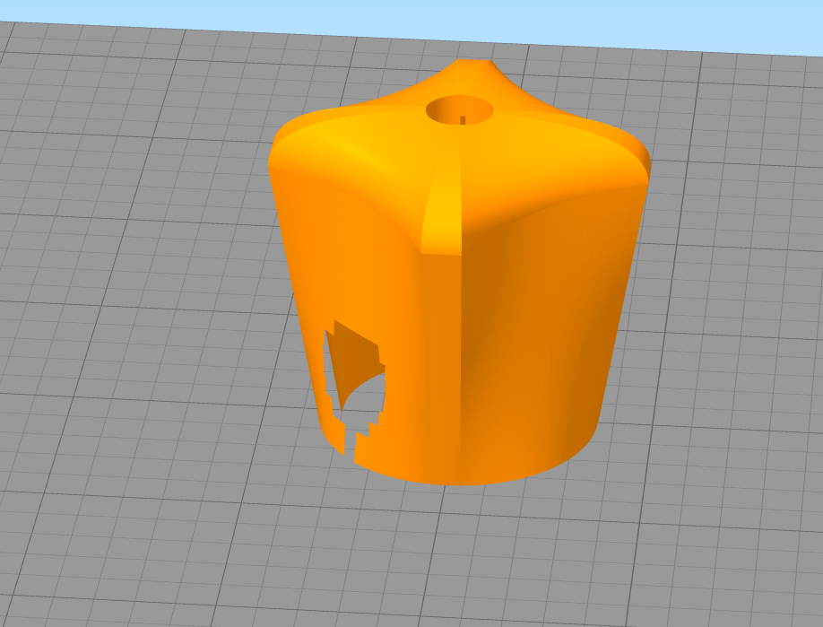
The model must not have holes, i.e. missing triangles through which you can see the inside of the model. Such a model is not treated as a solid, but as a surface of zero thickness, which of course cannot be obtained. The so called inverted normal are also a problem. They appear when part of the triangles in .STL models is turned inside out and vice versa. Slicer is unable to interpret where the center of the model is, which can result in 3D print failure.

A similar problem may arise with a model that contains intersecting or overlapping walls. A well-prepared model must be free of the above mentioned errors.
How to avoid geometry errors?
The best way to get rid of geometry errors in the 3D model is to avoid them during design. Professional design programs almost automatically prevent such errors as they usually work on solid models. Free programs do not have such “safeguards” and require more thoughtful work. The principle is simple: the more complex and complex the model, the greater the chance of geometry errors. To reduce the probability of their occurrence it is necessary to work on single primitives (simple basic solids such as: cube, cylinder, sphere, torus, etc.), which during modeling, through pulling, scaling, deforming and other operations are transformed into target models.
If it is necessary to work on several solids, they should be connected with each other by means of Boolowski operations (CSG). This avoids most of the errors during model creation. Errors can also occur when modifying previously downloaded 3D models from the Internet. Editing these objects can lead to overlapping walls or holes in the model. Such errors are difficult to detect with the naked eye and cause serious printing complications.
Checking the geometry of the model:
To verify the correctness of the model, specialized software is used which automatically checks whether the model has geometry errors, fixes them automatically or indicates their location when automatic repair is not possible. Unfortunately they are not free in their full versions. However, they are worth their price. In addition to fixing bugs and verifying the geometry, they allow, among other things, to smooth the surface by compacting the grid of triangles, or to reduce the “weight” of the file by replacing multiple triangles, lying on the plane, with one. In addition, they allow the so-called shell, i.e. emptying the model leaving the same wall thickness throughout the model and the model itself empty inside. This is recommended with some 3D printing technologies in order to save material. Some programs have modules that allow you to prepare a file for 3D printing just like slicers.
Simple 3D modeling programs can also have some features to fix geometry errors, usually tools to patch holes and remove overlapping walls, but these algorithms work within a fairly limited range and cannot deal with more serious errors. The slicers themselves can also have very simple solid verification modules. They usually only check and fix the problem with reversed normal ones and only in very uncomplicated cases. Therefore, you should carefully check the print preview before releasing the file to the printer.
2. an attempt to interpret the damaged model by the slicer and the damaged surface in the preview
A well prepared 3D model with the guidelines and meeting all requirements will make the 3D printout cheaper , both due to lower material consumption (double walls may unnecessarily increase the surface area of the model) but also due to the lack of necessity to work on the repair of the model later. Correctly prepared model wit uniform surface of the model, will improve the aesthetic value of the print and increases its mechanical strength.
